In the world of industrial automation and control systems, communication protocols play a crucial role in ensuring seamless data exchange between devices. Modbus started as a protocol used in Modicon, now Schneider Electric, PLCs in the 1970’s. It was adopted across the industry for its clarity and simplicity. With any protocol, including and especially with Modbus, there are areas where the parties to the communication, the client and server, can interpret the bit stream of data differently once exchanged because the Modbus protocol specification does not speak to those interpretations.
For example, whether addresses start at 0 or 1, the order of 8-bit bytes within 16-bit words, handling of 32-bit floating point values, and more can result in seeing data values that are different from the expected. You may even find that the driver is not reading the location you thought it was. The driver isn’t broken; there is most likely a configuration issue involving addressing or data formatting/interpretation. You might even be comparing the behavior of two different Modbus Clients and reading back different values for the same register address in a device depending on how those clients interpret the data.
The TOP Server Modbus Client drivers included in the TOP Server Modbus Suite include configuration options to handle the potential variabilities. The configuration options empower you to address and interpret data in varying ways to accommodate all your devices that use Modbus.
In this blog post, we dive into the details of the TOP Server Modbus Device Properties, with a focus on the Data Access and Data Encoding configuration settings. The options we discuss will apply equally to the Modbus RTU Serial Client and Modbus TCP Ethernet Client drivers. The Modbus ASCII Client driver also supports most of these settings as applicable to that protocol variant.
Data Access Settings
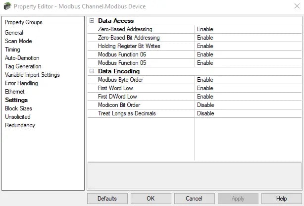
The Data Access settings in the TOP Server Modbus Device Properties serve as the roadmap for communication between the TOP Server and Modbus devices. These settings dictate how information is addressed, retrieved, and manipulated, essentially paving the way for a smooth exchange of data. Let's break down the key components and then the options.
With devices that use Modbus, different documents and users speak in different terms. We do not want to get too complex here, but the terms Offsets and Register Addresses can mean different things. Ultimately, we are addressing physical memory in a device, and the device manufacturer may address their memory areas with an offset into that area starting at a value of 0 or 1. Modicon/Schneider PLCs internally start their memory offset numbers with a 0. Other devices are a mix – some start at 0, some start at 1.
Complicating this is the fact that Modicon/Schneider PLCs will refer to a holding register as 4xxxxx memory, and they start at 40001. See the challenge? If the PLC programmer refers to the first holding register as 40001, but the internal memory starts with address 0 – to get the value of 40001, the driver must ask for physical memory offset/address 0. In many non-Modicon/Schneider PLC devices though you’ll never see a 4xxxxx listed. Instead, you’ll see a table of “Offsets into Holding Register Memory,” which may or may not be the actual internal memory location, it may be an implied “Stick a 4 in front of the number below and that’s the Modbus Holding Register Address.”
The good news for you is that with one check box setting, the TOP Server driver can take care of this translation for you. In the prior example you put in 40001 and TOP Server will use the right internal memory offset (0 or 1) based on how you configure the driver.
Zero-Based Addressing: The first place to look if you think you are reading the wrong value will be this setting. If your device documentation isn't clear and you are using trial and error testing, it's best to start with a single 16 bit holding register and make sure you are getting the expected value. You could also use a bit (inputs/1xxxx or outputs/0xxxxx) or an input register (3xxxxx) if you want. It's rare for the four typical Modbus memory types to not all use the same setting for zero-based addressing.
If the place you are seeing the problem is only in 32 or 64 bit data types like DWord, Float, etc, but your 16-bit registers are showing the right values, then your addressing base, 0 or 1, is probably right, but you have a data interpretation issue which we will address later in this blog in the Data Encoding settings.
When this property is set to be enabled, as it is by default since that’s what the Modicon/Schneider Electric PLCs do, the driver will take the address you configure in TOP Server will subtract 1 to get the true memory offset and use that in the protocol “under the hood” when communicating with the Modbus device so you don’t have to worry about it. This means the tag address listed as 40003 in TOP Server will map to the internal device holding register memory offset 00002.
Conversely, when this setting is disabled, the tag address in TOP Server won’t have 1 subtracted and for 40003 the driver will try to read the device physical memory offset 3. If set improperly, the impact will be that is the user will be retrieving data one register off from what they might be expecting.
Below is an example of this setting in action. If we focus on the tag values first, we can see how in both images we are observing the same 3 values. However, if we now look at the addresses in the “Item ID” column, you will notice they are all one off from the other example, but still provide the same value.
Zero-Based Disabled (aka One Based Addressing)
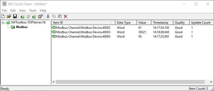
When Zero-Based Addressing is disabled, there is no offset 0, the first offset is 1, and our tag addresses of 40002, 40003, and 40004 have the values of 61, 39321, and 95 respectively and are actually reading from memory offsets 0002, 0003 and 0004 in our PLC.
Zero-Based Enabled

However, when Zero-Based Addressing is enabled, we are still receiving the values of 61, 39321, and 95, but instead from the tag addresses in TOP Server of 40003, 40004, and 40005 respectively, which are still reading from the same memory offsets 0002, 0003 and 0004 in our PLC.
This shows that we are pointing to the same physical memory offsets addresses in the device, but how the required Modbus Address changes in TOP Server depending on how this option is set.
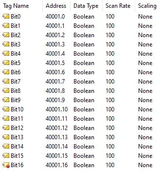
Zero-Based Bit Addressing: Within registers, there are memory types that allow bits within Words to be referenced as Booleans. This setting provides the same flexibility as the previous setting but applies to the individual bits within the addresses instead of the entire address. For instance, given we are referring to a Word (16-bits), if zero-based is enabled, the first bit will begin at 0 and range to 15. If zero-based were to be disabled, the first bit would start at 1 and range to 16.
To further represent this behavior, see the below screenshot where we have enabled Zero-Based Bit Addressing. Because of this, the bits range from 0 to 15, so we observe the tag address of 40001.16 as being invalid (as indicated by the red warning sign) because bit 16 does not exist in this context. If we disabled this setting instead, the bit 0 address would become invalid because the range becomes 1 to 16.
Holding Register Bit Writes: Holding registers can be seen as containers for a sequence of bits, each representing a specific binary state/value (0/1). The Holding Register Bit Writes option allows users to precisely modify these bits. This comes into play in situations where certain devices support a special command that manipulates a single bit within a register. Many devices do NOT support the extra optional Modbus function code (22 Decimal, 0x16 Hex) to do this! Consult your device documentation first if you need to do this. Enabling this feature directs the server to modify only the targeted bit in a single command, providing a seamless approach to bit-level communication.
Conversely, disabling this feature, which is the product default, allows for a broader, Read/Modify/Write operation that must be used with care. When the special function is not available and this Read/Modify/Write operation is performed, the driver reads the 16-bit word, changes the bit you specify to the value you set, and then writes that entire word back to the device. The risk is if the program or operation in the device changes a different bit than the one you are changing, during the time between the read and the write back. The driver writeback could overwrite that change. There is nothing any driver from any developer can do about this, as the safest solution is for the device to support the special Modbus Function code 22 Decimal/0x16 Hex for single bit writes.
Modbus Function 06: Modbus Function 06 is used for writing data to a single holding register data in the device. In most cases, the driver can switch between functions 06 and 16 depending on the scenario. Function 06 is only used for writing a 16-bit value to a single register, where function 16 is used when writing to more than one 16-bit holding register in a single command in the protocol. For standard Modicon PLCs, both functions discussed can be used without problem. However, there are many non-Schneider Electric PLC Modbus devices (also called third party devices in this blog), where only function 16 is used therefore, this setting would need to be disabled.
Modbus Function 05: Modbus Function 05 is utilized for writing output coil data. The driver intelligently toggles between functions 05 and 15 based on the number of coils being written. Function 05 will be used when writing to a single coil, and function 15 when writing to an array of coils. Like function code 06 discussed above, with standard Modicon/Schneider Electric PLCs, both functions can be used. Many third-party Modbus devices exist where only function 15 is used to write via an array, regardless of the number of coils, including just one. Users can enable or disable Modbus Function 05, aligning with the unique demands of their devices, especially those supporting only Modbus function 15 for writing to output coils where this setting should be disabled.
For a deeper understanding of Modbus Function Codes, please see our previous blog on Demystifying Modbus Function Codes. This blog discusses the Modbus functions codes that TOP Server uses to read and write the different types of Modbus memory addresses and how they correspond to the actual addresses your client is requesting.
Data Encoding Settings
Data Encoding settings in the TOP Server Modbus Client drivers determine how the information is represented and understood. These settings influence how the server reads, interprets, and communicates data values. Once you've confirmed you are using the right setting for 0 or 1 based addressing, these settings are the next ones to work with. This especially applies to 32-bit and 64-bit data types, including floating point values.
Modbus Byte Order: By default, TOP Server employs what Modicon/Schneider Electric PLCs use as their default for encoding of data within 16-bit words, also called Registers, in Modbus. The default setting of enabled, often referred to as Modbus byte ordering, aligns with Modicon/Schneider Electric PLCs and many third party Modbus-compatible devices. If third parties do the same as those PLCs, then Modbus operates as a standardized communication protocol, ensuring a smooth and straightforward exchange of information. However, there are devices that deviate from this standard Modbus byte order and use Intel byte ordering. In those cases, this setting should be disabled. This is all covered in much greater detail in the driver help files installed with TOP Server.
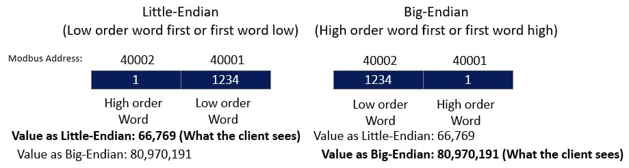
First Word Low and First DWord Low: These settings play a pivotal role in determining the data encoding of 32-bit and 64-bit values. For 32-bit data types, where two consecutive 16-bit register addresses are used, users can configure whether the driver reads the first word as the low or high word. Similarly, for 64-bit data types using four consecutive 16-bit register addresses (or two 32-bit DWords), users can decide whether the driver reads the first DWord as the low or high DWord. This concept is often referred to as “Endianness” and can have a large impact on what your client sees versus what it expects to see. By default, this is set to enabled for both settings, which can be referred to as “Big-Endian” and disabling these would give us what is known as “Little-Endian.” The term comes from “Big End In” or “Little End In” where “Big” means the most significant word, and “Little” means the least significant word. These terms are also sometimes used with Byte order as well: “Big or most significant byte” vs “little or least significant byte”.
This being set incorrectly can sometimes lead users to believe that they are reading from the wrong memory location, where it is simply an interpretation of data issue. The image below shows what effect it can have on what the client sees in different scenarios.
Modicon Bit Order: In binary representation, data is organized as a sequence of bits. The MSB (Most Significant Bit) is the leftmost bit, holding the highest value in the binary number, while the LSB (Least Significant Bit) is the rightmost bit, representing the lowest value. This ordering convention plays a crucial role in how data is interpreted and processed. Modicon Bit Order can reverse the bit order on reads and writes to registers. By default, which like other settings is based on what Modicon/Schneider Electric PLCs use, this setting will be disabled, making the last bit the most significant. However, enabling this setting will result in that reversal discussed, making the first bit the most significant as shown below.
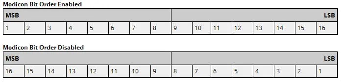
The reversal option ensures that TOP Server and the Modbus devices share a consistent understanding of how bits are arranged within registers. If you are seeing totally wrong values for a read, this is possibly the problem, but remember the problem could also be addressing.
Treat Longs as Decimals: This setting determines whether the driver encodes and decodes double-precision unsigned Long and DWord data types as values within a range of 0 to 99999999. The setting ONLY applies to those data types. By default, this is disabled. However, when enabled, this feature transforms the interpretation of these data types into values within that range mentioned, from 0 to 99999999. This format dictates that each word within the encoded data represents a value between 0 and 9999. Values read above the specified range are not clamped, or limited, to the maximum; however, it's important to note that the behavior in such cases is undefined. Users should exercise caution when dealing with values outside the designated range.
Decoding Process for Values Within the Range:
For values read within the specified range, the decoding process follows a specific formula:
[Read Value] = HighWord * 10000 + LowWord
This ensures accurate interpretation of the encoded values within the defined range.
Handling Values Greater Than the Maximum:
When writing values greater than 99999999, a clamping mechanism does come into play. All written values exceeding the maximum range are clamped to the maximum value.
Encoding Process for Written Values:
All values written are encoded using the formula:
Raw Data = [Written Value]/10000 + [Written Value] % 10000
This encoding formula ensures an accurate representation within the specified range during the encoding process.
In summary, this setting influences how certain data types are encoded and decoded within a specified range, with considerations for handling values outside that range and specific formulas for decoding and encoding within the range.
Conclusion
In this post, we took a deep dive into all the Modbus settings at the Device Properties level. As you can see, these settings can be very important in how TOP Server retrieves and interprets the data from your Modbus devices to ensure that your data comes from the right location in the device, and that it is presented right to the user.
By developing a good understanding of the intricacies of the Data Access and Data Encoding settings, users can tailor our TOP Server Modbus communication driver precisely to meet the unique demands of their industrial automation systems. Additionally, by being aware of common issues and employing effective troubleshooting strategies, users can ensure reliable operation of their Modbus communication infrastructure. If you run into any problems or have any questions regarding the configuration of the settings discussed, please feel free to contact our technical support team.
Don't forget to subscribe to our blog to find out about the latest updates to TOP Server and for other useful tutorials and resources as well as take a look at our other Modbus related Technical Blog posts.
Ready to try TOP Server with your devices? Download the fully-functional free trial.