If you’re a user of the Allen-Bradley ControlLogix Ethernet driver in TOP Server for AVEVA, you may be familiar with the different protocol modes available during device configuration. The three distinct options of Symbolic, Logical Blocking, and Logical Non-Blocking provide users with advanced control over how data is read and addressed from the controller.
Configuring protocol modes is usually only suggested for advanced users who have a solid understanding of each mode, and how their Logix programs are structured. To that end, continuing our Tech Support Corner blog series, this blog post will break down each of these protocol modes, while exploring their benefits and drawbacks, to provide you a clear understanding of each protocol. This post will provide the advanced knowledge needed in a usable way to best serve your own project!
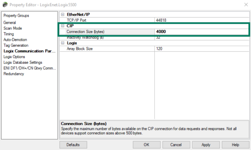
With ControlLogix Ethernet in TOP Server for AVEVA, there are a number of best practices and methods for optimizing your configuration to ensure the best performance. When configuring a new device that uses the ControlLogix Ethernet driver, you will be given the option to choose which protocol mode you would like to use. By default, this is set to use Logical Non-Blocking. This will block together requests for all individual client/server tags at a fixed request size. This is accomplished using multi-request packets that allow for multiple requests to be sent in a single transaction, providing drastic improvement in performance over single item transactions. The only limitation of Logical Non-Blocking is the number of data bytes that can fit in a single transaction, as the default is set to 500 bytes for maximum compatibility with older CPUs, but can be increased to as large as 4000 bytes for some CPUs as we will cover later in this post.
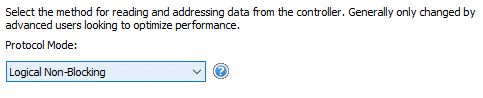
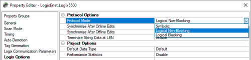
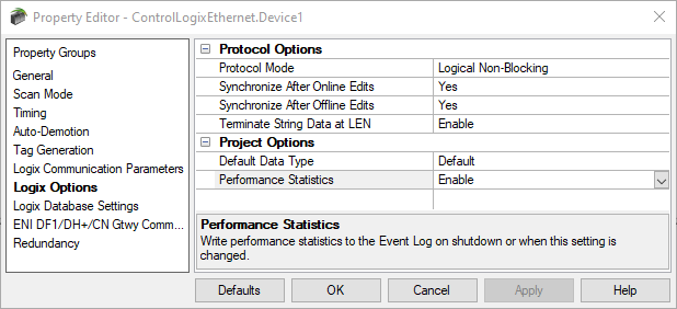
If you want to change the current protocol mode of a device already configured, you can find the settings by double-clicking the device you wish to modify. This will display the device property editor. Selecting “Logix Options” on the left menu bar will allow for the protocol mode to be changed.
What are the different ControlLogix Protocol Modes?
The TOP Server ControlLogix Ethernet driver supports three different protocol modes: symbolic, logical non-blocking and logical blocking. Each protocol mode has specific circumstances where it is the most appropriate option to select for your application.
1. What is ControlLogix Symbolic Protocol Mode?
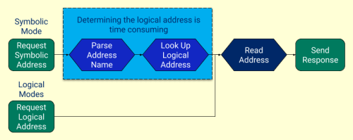
The Symbolic Protocol Mode is the standard Allen-Bradley CIP (Controller Interface Protocol) method that requests each tag individually with its full ASCII character name. For example, a tag address could appear as simple as “OvenTemp1”. This allows for tags to be named in a way that is easily read and understood. While this is convenient for the users working with these tags, it can take significant overhead for the device to manage. As tag names become longer and more complex, the operation will take more overhead to complete. Additionally, longer symbolic tag names with this mode result in more requests being necessary to the device to return all of the data being requested due to the previously mentioned limit on the bytes per transaction.
2. What are ControlLogix Logical / Physical Protocol Modes?
These modes address the actual memory locations where tags are stored. To achieve this, TOP Server must map the whole tag-name index against the ControlLogix memory map every time the device is connected. Each ControlLogix tag (member for structures/element for arrays) has a physical address returned from the controller during the initialization upload sequence. The initial mapping will slightly increase the startup time of TOP Server as it builds the tag address database (how much is relative to the total size of your tag database in the controller). However, once complete, this method is extremely efficient, as it eliminates the need for parsing and looking up the complex string names used in Symbolic.
What is ControlLogix Logical Non-Blocking Protocol?
This mode follows the logic from the diagram above but is unique in how it requests the memory address. It requests data in similar fashion as symbolic mode, each tag is requested individually while utilizing the advantage of Multi Request Packets. Each tag in the data structure is requested individually by its corresponding logical addressed that is created. These individual addresses are then grouped together in a packet to retrieve the corresponding data.
What is ControlLogix Logical Blocking Protocol?
Blocking refers to requesting whole structures of data from the PLC all together. Structures in a PLC are like arrays but hold multiple datatypes. This is an extremely effective way of bringing large quantities of data back from the ControlLogix. However, regardless of how many elements of a structure are requested from clients at the time, the entire block of data is retrieved on every read request. If you want to access every tag in your PLC, or most of a Logix tag structure, this is the most efficient method.
Guidelines for Selecting The Right ControlLogix Protocol Mode
Now that you know about how each protocol mode works, how should you select the right one for your project?
There are a few questions you should ask yourself when determining which method to implement:
- How many tags am I going to use from the PLC?
- Is the connection stable and constant?
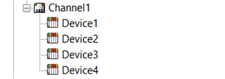
- How are the channels and devices configured? Are there multiple devices under one channel?
If your client is only requesting a small percentage of the overall tags from TOP Server, Symbolic mode may provide the most efficient communications. As Symbolic mode only requests the individual tag names when requested. This also skips the potentially high (depending on tag count) initialization time related to both Logical modes.
Having a client that is continuously connected to TOP Server is greatly beneficial for performance when using either of the Logical protocol modes. Since Logical modes query the whole PLC memory during initialization and map tags to the associated memory location, having an unstable connection or a client that often disconnects would require this operation to be repeated every time it reconnects. With large projects, this initialization time can be rather long. However, once the memory has been mapped out, communications using the Logical protocols are very efficient.
Now that we have a better understanding of basic project considerations, and how each protocol works, we can simplify our choice by following these guidelines.
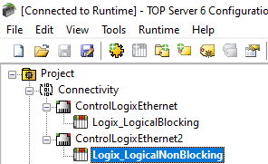
For the best communications performance to your device, we always recommend putting each device under its own channel. However, it’s absolutely necessary to use Symbolic mode if your project does require multiple devices under one channel (such as telemetry scenarios where there is a shared master radio).
When using either of the Logical Protocol Modes, it is imperative that each device be configured under a separate channel. Failure to do so will result in slow performance due to the TOP Server process of polling devices sequentially when defined under a single channel, combined with the pre-mapping of addresses that occurs with the Logical Protocol Modes (i.e. this mapping will happen every time the driver reaches every device in the polling sequence, as opposed to one time on startup).
When to Use ControlLogix Symbolic Protocol Mode
 Symbolic Protocol Mode is recommended for systems where the TOP Server will be restarted frequently, where only a small fraction of the total tags are requested, or when multiple ControlLogix controllers must be configured under a single channel (commonly found in telemetry applications).
Additionally, over slower networks such as cellular telemetry, using Symbolic Protocol is recommended for the best performance. The logical/physical address mapping process doesn't typically work well over telemetry or slower networks, which can result in poor performance and bad communications. Since Symbolic Mode includes the tag name in each request, it's more resilient over slow networks.
When to Use ControlLogix Logical Protocol Modes (and Which One)
Logical Protocol Modes are recommended in systems where higher quantities of tags are being read from the controller, and when the TOP Server will be left running for long periods of time without restart and multiple devices under a channel are not necessary. The general guidelines for choosing one of the Logical Protocol modes are:
- Logical Blocking - Will read entire data structures of tags being requested and is recommended for projects where more than 50% of objects/structures are being read from the controller.
- Logical Non-Blocking - Will request individual memory addresses and not read entire objects/structures. This mode is recommended when less than 50% of data structures are being requested from the controller.
Additional ControlLogix Flexibility Features Help Optimize Performance
The differences between each protocol mode provides TOP Server the flexibility to work efficiently with a wide range of project scenarios. Beyond the protocol modes, though, the TOP Server ControlLogix Ethernet driver provides a number of other features to enhance ease-of-use and performance on your Logix projects.
Automatic Tag Generation and the ControlLogix Ethernet Driver
Using Automatic Tag Generation in the device settings is a quick and easy way to access all available tags from a device. Even if you’re not going to use the auto tag generation to maintain a static tag database in TOP Server for connecting your client application to your PLC tags, auto tag generation can be a big help with ensuring your address syntax is correct for those PLC tags. Once you pull all of your tags into the TOP Server, you can quickly delete the group(s) and tag(s) that you won’t be using.
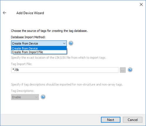
A CSV Export and Import can also be performed if you find editing the tag database easier this way or for creating an import file for your client application if you prefer to use dynamic tag references instead of having static tags in TOP Server.
Configurable ControlLogix CIP Connection Size Reduces Number of Requests
As I mentioned earlier, the CIP Connection size defaults to 500 bytes, which contains either the symbolic names or the logical address pointers of multiple PLC tags that you would like to request.
However, if the following is true of your ControlLogix 55xx or CompactLogix 53xx, you can increase the CIP Connection size to a maximum of 4000 bytes:
- Running firmware version 20 or later
- Using an Ethernet bridge/module EN3x, EN2x, or EN5.x
Older Ethernet modules like ENBT and ENET do not support this feature; if you attempt to change this value on an unsupported device it will automatically fall back to the default setting. Increasing the connection size allows for more bytes to fit into each packet sent, increasing communication efficiency. If you can maximize the CIP connection size, you can effectively service your client’s tag requests up to 8 times faster.
Performance Tuning Options for ControlLogix Ethernet
With any programmable controller, there are unique ways for optimizing system throughput. This is especially true for ControlLogix controllers. The TOP Server ControlLogix Ethernet driver has a variety of ways to enhance overall performance and system communications. We’re going to explore a high-level overview of some tips you can use to help get the best performance from your project.
Using Multiple Channels and Devices for Concurrent ControlLogix Connections
Where possible, configuring multiple TOP Server devices for communications to the same ControlLogix controller can provide great performance benefits (i.e. making multiple connections to the same device. It’s always important to consider the overall communications load on your ControlLogix controller when determining whether or not to make multiple concurrent connections to the same controller.
Ideally, all of your communications with a Logix controller would go through TOP Server for the best and most efficient performance. This minimizes the number of connections and requests to the controller, resulting in the best performance. If other OPC servers or communications drivers (possibly native drivers in an HMI or SCADA package) are also connecting to your controller, you’ll want to determine how many connections already exist and how much load they are placing on the controller since a Logix controller doesn’t have an infinite amount of time just for communications requests (it is, after all, ultimately designed to execute logic and control your process).
However, if existing connections to your controller are at a minimum such that overloading the controller with too many connections and read/write requests isn’t a concern, you can designate one or more devices for Logical Blocking purposes and one or more devices for Logical Non-Blocking purposes. This provides some tags with better performance using Logical Blocking, while others will get better performance using Logical Non-Blocking.
In this architecture, you would have your client application request tags from a device using Logical Blocking mode when the majority of the elements of a structure for that tag are required. For all other tags, your client would access the topic for the Logical Non-Blocking mode device in TOP Server.
Optimizing ControlLogix Communications with Performance Statistics
To assist with tuning your configuration to get the best performance communicating with your ControlLogix with TOP Server, the ControlLogix Ethernet driver also includes performance statistics. When enabled, performance statistics generates a set of benchmark and statistical data that provides insights into the performance using the current settings and configuration.
It is recommended to only enable performance statistics while you’re tuning your configuration and settings since it can decrease the server's long-term performance if left always enabled. This is why performance statistics default to being disabled.
To enable the Performance Statistics feature, access the Device Properties for your ControlLogix device in TOP server, navigate to the Logix Options section and set Performance Statistics to “Enabled”.
The resulting statistics are gathered during normal communications using your current settings in TOP Server with connectivity from your client/clients requesting data from the Logix controller. Those results are output to the TOP Server Event Log upon shutting down the TOP Server runtime – so once you’re performed the desired communications read/write operations from your client applications, you can restart the TOP Server runtime and then go to the TOP Server Event Log at the bottom of the TOP Server Configuration interface.
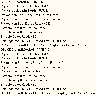
The statistics cover device-specific, channel-specific and driver-specific metrics – which metrics you need to review will depend on your particular application. In general, though, driver-specific statistics provide a measure of the overall project's performance with respect to Logix communications, whereas channel and device specific statistics are most relevant while actually attempting to tune communications for specific devices.
Some examples of questions the performance statistics can help you answer include:
- Will moving 10 certain tags from Device A to Device B increase the performance of Device A? (assuming, of course, that you have more than one device configured in TOP Server to the same Logix controller)
- Will moving Device A from Channel 1 to Channel 2 increase the performance of Channel 1? (assuming that you have more than one device on Channel 1 – which should only be true if you’re using Symbolic mode for the reasons discussed earlier in this post).
You can explore more details of this setting in the ControlLogix Ethernet driver help file under Performance Optimizations > Performance Statistics and Tuning.
Below are a few key considerations to keep in mind when adjusting your project to achieve better performance. The following table is an example of how performance improvements could be made when implementing these practices (your results will vary depending on your tag count, client count, update rate and other variable factors).
- Devices should have a dedicated channel. More than one device should not be put on a channel unless necessary for the reasons previously discussed in this post, such as telemetry applications potentially, and never when the device is configured to use one of the Logical protocol modes.
- The same Logix tag should not be referenced across different devices configured to connect to the same Logix controller (this adds unnecessary additional overhead by requesting the same tag multiple times).
IMPORTANT: The table below is just an example, and is not meant to say these are the fastest performance levels possible with this driver! Overall communications throughput is a function of many variables including PLC CPU, program loading, CPU time slice settings for communications, user network, and more.
|
Server Project Layout |
Driver Performance (Reads/Second) |
Improvement Over Symbolic |
|
Single Channel / Single Device / Logical Blocking |
5972 |
768% |
|
Single Channel / Single Device / Logical Non-Blocking |
3705 |
476% |
|
Single Channel / Single Device / Symbolic |
777 |
N/A |
|
Single Channel / Multiple Devices w/ Tag Division by Ideal Protocol Mode |
6126 |
788% |
|
Multiple Channels / Multiple Devices w/ Tag Division by Ideal Protocol Mode |
6426 |
827% |
A detailed example of performance tuning a TOP Server application using Logix performance statistics and the testing capabilities of the OPC Quick Client that installs with TOP Server with step-by-step instructions is included in the driver help file under Performance Optimizations > Performance Tuning Example.
To summarize, whether you’re a long-time user of the Allen-Bradley ControlLogix Ethernet driver or just starting out, we hope this blog has provided a stronger understanding of its unique protocol modes. If you’d like to test connectivity to your own Allen-Bradley ControlLogix controller, you can follow our Quick Start Video Guide. The latest version of TOP Server is available as a free trial here, all features are enabled during a 2-hour demo period which can be reset by simply restarting the runtime.
Have Questions? Contact us with your questions and we'll be glad to help.
And don't forget to subscribe to our blog for other useful how-tos, tips and updates like this.