In a prior blog post regarding redundancy, we learned how critical it is to plan for redundancy in the Industrial Automation space. We covered how the TOP Server Media-Level Redundancy Plug-In facilitates duplicate or backup systems used to maintain reliable communications with the critical components in your environment which in turn minimizes data loss and increases the availability of your critical industrial data.
To review, the TOP Server Media-Level Redundancy Plug-In supports two types of redundancy: Communications Path Redundancy and Device Pair Redundancy. Both modes of redundancy can be used together or separately to provide the reliability necessary. For more information regarding the two types, please refer to our previous post, Insuring Data Availability with the TOP Server Redundancy Plug-In. That post also covered in detail Device Pair Redundancy which leverages two identical devices to allow for redundancy.
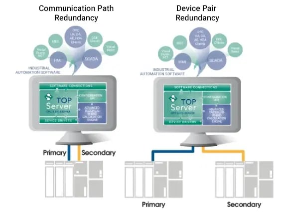
For this post, we will step through configuring Communications Path Redundancy. Communications Path Redundancy is when TOP Server is configured to communicate with a device over multiple communication methods. For example, imagine you have a device that supports both Ethernet and Serial communication. Communications Path Redundancy allows you to set the primary source of communication as Ethernet and then also assign the device to use Serial communications should the Ethernet network become unavailable. Or a device could have redundant Ethernet connections on the same PLC and switching would be between them.
To enable Media-Level Redundancy, select the plug-in during the installation of TOP Server as shown here. If TOP Server is already installed, run the installer under “Modify” to add the plug-in.
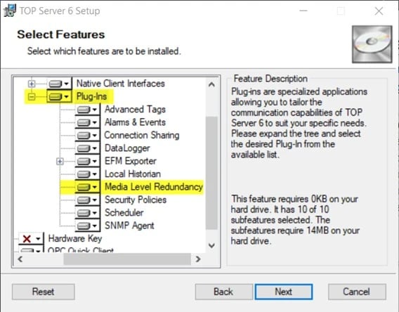
Enabling the Media-Level Redundancy Plug-In with the installer will add a “Redundancy” tab in the Device Properties of the primary device. You configure redundancy under this Property Group, regardless of whether you are using Communications Path or Device Pair Redundancy.
Configuring Communications Path Redundancy
In our last post we configured communication to two separate devices running the same logic, which allowed for failure over to the secondary device if the primary device had failed.
Before moving forward, it is important to understand that in TOP Server a Channel represents a communication medium from the PC to one or more external devices. A Channel can be used to represent a serial port, a card installed in the PC, or an Ethernet connection thread which may go to one or more devices. We will be using a serial port and an Ethernet connection as our communication connections for our redundancy.
Unlike Device Pair Redundancy, where you configure two separate devices in TOP Server, Communications Path Redundancy requires two different communication connections to the same device. Either option will require two separate Channel/Device pairs serving as the Primary and Secondary data sources.
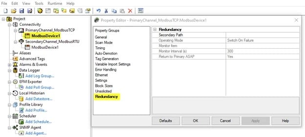
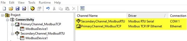
In the below image you can see we have configured both a “PrimaryChannel_ModbusTCP” and a “SecondaryChannel_ModbusRTU”, where our “PrimaryChannel_ModbusTCP ” is configured to communicate via Modbus Ethernet TCP/IP to device “ModbusDevice1” and our “SecondaryChannel_ModbusRTU ” is configured to communicate via Modbus RTU Serial to that same physical device.
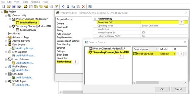
Now, let’s set SecondaryChannel_ModbusRTU.ModbusDevice1 to be the backup to PrimaryChannel_ModbusTCP.ModbusDevice1. This is where you specify the explicit, unaliased path to the “device” serving as backup should the primary device fail. In our case, our device is the same, but our communication type is different.
Setting a Secondary Path:
- Open the Device Properties of PrimaryChannel_ModbusTCP.ModbusDevice1 and navigate to the Redundancy tab.
- Click the ellipsis button in the Secondary Path field to open the “Select a Device” window.
- Select the SecondaryChannel_ModbusRTU.
- Select the ModbusDevice1 and click OK.
Now it is time to select the Operating Mode. This specifies how the active device is chosen at runtime. There are 4 options: Switch On Failure, Switch On Trigger, Primary Only, or Secondary Only. For more information regarding the four types of Operating Modes, please see our FAQ on TOP Server Media-Level Redundancy Operating Modes.
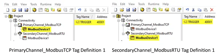
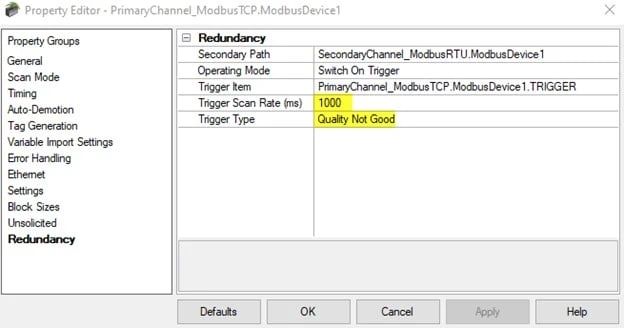
For this example, we will select the Switch On Trigger Mode. As a reminder, this is when the server monitors a configured trigger item. When the trigger condition becomes true, communication will switch over to the configured secondary device. If the condition is false, communication will remain on the primary device. For the Trigger Item to be monitored successfully, it must be configured under both defined devices. See below image for clarity:
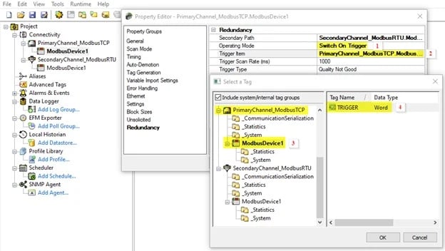
Selecting the Trigger Item:
- Open the Device Properties of PrimaryChannel_ModbusTCP.ModbusDevice1 and navigate to the Redundancy tab. Set the Operating Path to Switch On Trigger.
- Click the ellipsis to open the “Trigger Item” window.
- Select the device configured under the PrimaryChannel_ModbusTCP.
- Select the Trigger Item you would like to monitor.
Next, you will need to specify the Trigger Scan Rate (ms). The valid range is 0 to 99999990 seconds. For our example, we have left this at the default of 1000 ms.
Lastly, define The Trigger Type. The Trigger Type options are:
- Quality Not Good – the failover occurs if the Trigger Item has any quality besides Good.
- Value – the failover occurs when the Value of the Trigger Item is equal to, not equal to, greater than, or less than the specified value.
- No Data Change – the failover occurs when the value of the Trigger Item does not change for a certain amount of time, specified in the Timeout (ms) property. This is helpful if your Trigger Item is a heartbeat tag that is expected to change its value at a certain interval.
For our example, we have selected Quality Not Good for our Trigger Type.
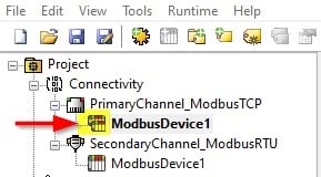
If all the above is configured correctly, a device with a redundant configuration will display the double device icon in the server Configuration Project View user interface.
You have now successfully configured a redundant communication path using the TOP Server Media Level Redundancy Plug-in. To learn how to monitor your redundant device, please refer back to our post, Insuring Data Availability with the TOP Server Redundancy Plug-In. There you will see that each redundancy definition has a set of specific read-only system tags created in the _System tag group for the primary device that can be used to observe the current failover status from any client application.
We hope this has shown you that TOP Server can provide an easily configurable solution for your redundancy needs. If you are interested in using the TOP Server Media-Level Redundancy Plug-In, please contact our support team with any questions. We will help you identify the best way to configure your project based on your use case. Don’t forget to subscribe to our blog to find out about the latest updates to TOP Server.
Other Related blog posts about Redundancy