I'm sure you've all at least had some interaction with Modbus, working in the automation industry. It's one of the most widely used protocols (if not the most widely used) in the world. Which is both its blessing and its curse, to some extent.
Given how long Modbus has been around and in use as an "open" protocol (starting in 1979), there have been many different interpretations of Modbus throughout the years. And with those different Modbus interpretations, much confusion about the different terminology for accessing data.
In this blog post, I will step through the basics of Modbus addressing including how offsets come into play, and how they affect what addresses to use in TOP Server for AVEVA applications.
Given the large number of Modbus protocol implementations in the world by almost as many different device manufacturers, device documentation can sometimes be unclear about what numerical address should be requested for a particular piece of data. So the intention of this post is to provide a somewhat standard explanation for how Modbus addressing works to make it easier to understand how to access the data in your Modbus devices using TOP Server.
Types of Modbus Addresses
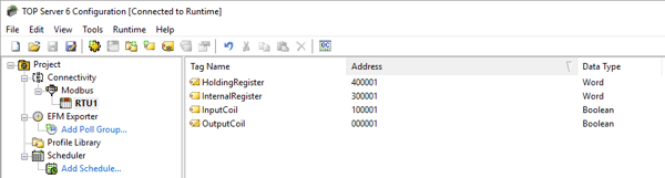
When we discuss the Modbus protocol and how to address particular locations of data, there are generally four different types of Modbus addresses:
- Holding Registers – 16-bit addresses with read/write access (4xxxxx)
- Internal Registers – 16-bit addresses with read only access (3xxxxx)
- Input Coils – 1-bit (Boolean) addresses with read only access (1xxxxx)
- Output Coils – 1-bit (Boolean) addresses with read/write access (0xxxxx)
Since some device documentation does not provide a detailed listing of Modbus addresses containing references to the type of address such as 4xxxxx or Holding Register, it is useful to think of Modbus addresses in terms of the type of data a particular address will contain and whether or not it can be read from and written to or only read from.
You may also see registers referred to as analogs or coils referred to as discrete or digital addresses due to the type of data they represent.
Offset Addressing: Is There a Difference between 4001 and 40001 and 400001?
As I've already mentioned, the Modbus protocol has been around for decades and is arguably the most widely used protocol for device communications in the world. That being said, with the birth of the Modbus protocol occurring when memory sizes were still relatively modest, the total amount of memory on a device in the late 70's was small compared to the large quantities of memory available today.
One of the most common questions asked when considering if the TOP Server Modbus Suite is compatible with a device is whether a particular address range is supported by TOP Server. The listed address ranges supported by TOP Server are as follows:
- Holding Registers – 400001- 465536
- Internal Registers – 300001- 365536
- Input Coils – 100001- 165536
- Output Coils – 000001- 065536
For many devices, the supported address ranges are much smaller than this. With holding registers, for example, in a device like this, an address of 4001 comes nowhere close to 400001 as a starting address. So how can TOP Server claim to have such wide support for Modbus devices given this data?
| Modbus Holding Register Addressing | |||
| Modbus Document Says: | TOP Server Says it Supports: | ||
| 4 | 001 | 4 | 00001 |
| 4 | 0001 | 4 | 00001 |
The TOP Server Modbus Suite does, in fact, support 4001, 40001 and even 400001. TOP Server effectively supports all Modbus addresses because Modbus uses a type of addressing referred to as offset addressing. Notice how, in the figure above, we have separated the starting number from the rest of the address. This is done to illustrate how an offset address works.
The address, “4001”, in the figure contains two pieces of information that we are interested in:
- What type of address should be requested from the device, represented by the starting number “4”. (Holding Register = 4)
- Which address offset should be requested from the device, represented by the rest of the number “001”. (Offset = 1)
Given this knowledge, let’s apply the same principle to the starting Holding Register address supported by TOP Server, “400001”.
- Our starting number is “4”, as before, meaning we are requesting a Holding Register.
- The remaining number, with the “4” removed, is “00001”, which is numerically the same as “001”, and represents the same Offset of “1”.
It is important to note that many Modbus devices may not support the full range of the data offsets that TOP Server supports. To avoid confusion when entering an address for such a device, TOP Server Modbus drivers "pad" the address (add a digit or digits) according to what was entered in the address field. As such, TOP Server automatically accounts for the “extra” zeroes in the middle and pads the address as needed.
This same principle is true for all of the different Modbus address types (Internal Register=3, Input Coil=1, Output Coil=0).
The reason this is true is because Modbus requests do not contain “400001” or “4001” when sent to the Modbus device when making a request. Only the address offset is sent as part of the command along with a function code that specifies a read or write operation and the type of Modbus address (Holding Register, etc.)
What Type of Modbus Address Do You Need?
That being said, the easiest way to determine what address to use in the TOP Server is to determine what kind of address you are trying to access in the device:
- Your documentation specifies that a particular piece of data will be analog (non-boolean/binary/discrete - such as 2,500 or 2.5689 or 58,535, etc.) and you will have read and write access to this data:
- You need to access a Holding Register.
- You would add a “4” at the beginning of any address offset that the documentation specifies.
- Your documentation specifies that a piece of data will be analog and you will only have read access to this data:
- You need to access an Internal Register.
- You would add a “3” at the beginning of any address offset that the documentation specifies.
- NOTE: It's entirely possible that a Holding Register might be documented as Read Only - the best way to know for sure is to confirm what Modbus Function Code is required to read from the address. If it's Function Code 3, it's a Holding Register. If it's Function Code 4, it's an Internal/Input Register.
- Your documentation specifies a Boolean/binary/discrete value (so on/off, true/false or 0/1) and you will have read only access to this address:
- You would need to access an Input Coil.
- You would add a “1” at the beginning of any address offset that the documentation specifies.
- NOTE: Bit access within registers is also possible - so rather than a Input Coil, you might still be referencing an Internal Register (just a bit within the register). Again, the best way to know for sure is to confirm what Modbus Function Code is required to read from the address. If it's Function Code 2, you know it's an Input Coil. If it's Function Code 4, you know it's a bit within an Internal Register.
- Your documentation specifies a Boolean/binary/discrete value and you will have read and write access to this address:
-
- You would need to access an Output Coil.
- You would add a “0” at the beginning of any address offset that the documentation specifies.
- NOTE: Bit access within registers is also possible - so rather than an Output Coil, you might still be referencing an Holding Register (just a bit within the register). Again, the best way to know for sure is to confirm what Modbus Function Code is required to read from the address. If it's Function Code 1, you know it's an Output Coil. If it's Function Code 3, you know it's a bit within a Holding Register.
View our related post for more specifics on Modbus Function Codes, and check out our TOP Server Modbus Addressing guide to view the above tips in a handy printable format.
Don't forget to subscribe to our blog to find out about the latest updates to TOP Server and for other useful tutorials and resources as well as take a look at our other Modbus related Technical Blog posts.
Ready to start accessing data from your own Modbus devices?