Have you ever been confused on the difference between Modbus offsets and addresses? I’m sure you may have configured different Modbus devices from different manufacturers who follow different documentation standards, especially for memory mapping. As we all know, that can certainly increase implementation time. In this blog post, we are going to dive into how offsets and addresses compare and differ to hopefully provide a better understanding, cutting down that configuration time when using TOP Server. Before we start comparing offsets and addressing, let’s first get an understanding of what both are.
The Basics
At the heart of Modbus communication lies the concept of addressing physical memory in a device. That is the role of offsets. In data structure terms, an offset is the distance of a specific location from the first memory location in the memory segment or section. Every memory data point in any computing device has an offset address. The address of that first memory location is very important since it designates the initial point in the device's memory space, establishing a baseline for subsequent offsets.
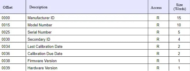
The image below shows an example of a Modbus holding register memory map that you may find in your own device’s documentation. For example, if we were looking to retrieve the firmware version of this PLC, we would have to point to offset 38. It’s important to note that in this device, the location of the first memory location is labeled as offset “0000”. We’ll come back to that later as not all devices start at 0!
Modbus addresses, also called Register Addresses in many PLC guides and documentation, add a layer of interpretation to these raw offsets. While offsets point directly to the physical memory locations, Modbus (Register) Addresses start with an integer number to specify the memory type, which was very intuitive for the original Modicon (Schneider Electric) PLCs when Modbus was created. A common example is the use of 4xxxxx addresses for holding registers. The “4” designates the Modbus memory segment type, holding registers in this case. For the typical Modicon/Schneider PLCs, the first holding register is denoted as 40001. This remains the same for input coils (1xxxxx), output coils (0xxxxx), or internal registers (3xxxxx).
Not all device documentation handles this clearly. We’ve seen device documentation that will only speak to “Holding Registers” and “Input Registers” without ever telling you that they mean 4xxxxx and 3xxxxx memory segments/areas respectively!
For simplicity in the blog post, any examples will reference holding registers (4xxxxx), but just be aware that everything mentioned will apply to all four of the typical Modbus memory types. For more information on Modbus Tag Addressing within TOP Server, please check out our blog post, Demystifying Modbus Register Addressing with TOP Server for AVEVA.
How It Impacts Your TOP Server Configuration
Not only do these addresses serve as convenient references for users and developers, but they are also used to tell the TOP Server Modbus drivers which type of memory to access. However, it's crucial to recognize that the actual memory offset may not always align with the register address, leading to potential confusion when interfacing with different devices. The impact of this is largely discussed in our Why Are My Data Values Wrong? - Exploring Modbus TOP Server Settings Blog.
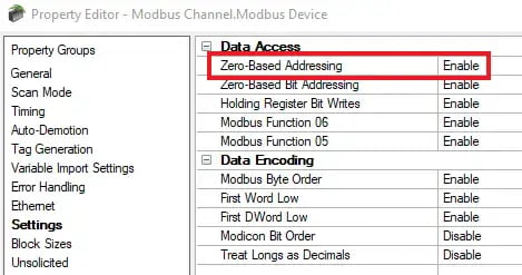
As a brief refresher, the zero-based addressing setting in TOP Server helps to alleviate this confusion. When enabled, as it is by default, it will take the address you configure in TOP Server and subtract 1 to get the true memory offset and use that when communicating with the Modbus device. Address 40003 in TOP Server will map to offset 2 in the device. Conversely, when this setting is disabled, the tag address in TOP Server won’t have 1 subtracted and for 40003 the driver will try to read the device physical memory offset 3.
Modicon/Schneider PLCs maintain a consistent and straightforward approach within the product line by initiating their memory offset numbers with 0. This uniformity simplifies communication and programming within their ecosystem. When a user refers to a holding register as 40001, the internal memory offset directly correlates to 0. This predictable relationship streamlines the development process for Modicon/Schneider users.
In contrast, some non-Modicon/Schneider PLC devices introduce variability by adopting different starting points for their memory offsets – either 0 or 1. This offset dilemma poses a challenge for users as they navigate varying conventions among different devices. As an example, say a third-party manufacturer has a Modbus device that starts at offset 1. A user will want to disable zero-based addressing and use the address 40001 to reference that first memory location of offset 1.
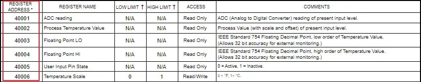
Something to also be aware of is you may see third party device Modbus memory maps use register addresses instead of just the offset. The example below shows this with the first register being 40001, instead of just listing the offset as 0001.
Where this can get confusing is if the hardware documentation is not clear what the number in the table column represents. The table above is great but imagine if they said “Location” as the heading, which we’ve seen. What if you are using Modbus Output Coil addresses, which start with 0? Is that a 0 because it’s an offset or because it’s a Modbus Output Coil memory segment/area? You can usually figure it out through looking at their documentation tables for Input Coils (1xxxx), Output Registers (3xxxx), or Holding Registers (4xxxx).
However, if the memory locations have a large number of locations, even the 1, 3, or 4 prefix doesn’t guarantee clarity. Be sure to read the descriptions as you will almost always find text that tells you the memory type. If you don’t, and they are saying “for function code X below are the addresses to use,” which by now you realize is an ambiguous statement, you can use our Demystifying Modbus Function Codes blog to map to the memory type that the function code uses.
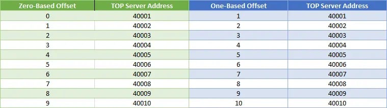
The following table visualizes the difference between the zero-based and one-based offset relative to the same set of tag addresses configured in TOP Server. As you can see, TOP Server addresses can be the same, but point to different offsets based on the configuration of the previously mentioned Zero-Based Addressing setting.
Below is a quick example of this difference in action. A Modbus device has been configured in TOP Server with a statically defined tag at logical address 40001. Issuing a single read twice on that tag, first with zero-based addressing enabled, and second with zero-based addressing disabled, has yielded the results below. In the Communication Diagnostics Logs, the Starting Register Offset is outlined in red, and the value returned from the PLC is outlined in green.
Read #1:
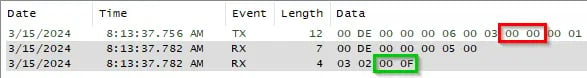
- Zero-Based Addressing Enabled
- Modbus Tag Address: 40001
- Offset = 00 00 (0)
- Value = 00 0F (15)
Read #2:
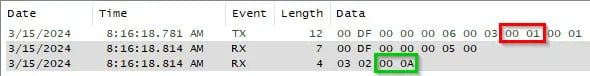
- Zero-Based Addressing Disabled
- Modbus Tag Address: 40001
- Offset = 00 01 (1)
- Value = 00 0A (10)
As we can see, toggling the Zero-Based Addressing property resulted in the driver reading a different physical address within the PLC, therefore returning a different value, despite the requested tag address within TOP Server remaining at 40001.
Another problem you may encounter if the base address is wrong is a ‘Bad Address in Block’ or ‘Illegal Device Address (02 Decimal)’ error in the TOP Server Event Log when reading Holding Register 40001. If the device uses 1 based addressing and you have your driver configured for 0 based addressing, the driver will use the function code for read holding registers with an offset of 0. The device does not have an offset 0! As a result, the device, if it has followed the Modbus standards for error handling, must reply with an exception code with value 2 to tell the client what is wrong. The driver is not broken, it did what it was asked to, but it was not consistent with the memory map of the device.
Please note that the TOP Server configuration options for your Modbus devices, such as zero-based addressing, are provided to allow you to configure the driver’s functionality to match the requirements of the device and not something you just get to choose based on your personal preference. Please refer to your device documentation or contact your device vendor to determine the proper configuration of these settings. TOP Server’s default device settings match the typical standards of Modicon/Schneider PLCs.
Conclusion
We hope this example has empowered your understanding of the difference in behavior around the logical address configured in TOP Server vs the physical offset within a device when enabling/disabling Zero-Based Addressing. For a deeper look into how TOP Server utilizes these addresses with Modbus function codes to process the protocol requests, I would highly recommend taking a look at our Demystifying Modbus Function Codes Blog, or any of the other blog posts mentioned.
As you have seen, Modbus offsets and addresses (or Register addresses) are very much linked with each other but can potentially cause much confusion without a proper base understanding of them. It is also very important to apply this understanding when looking at device documentation and configuring your TOP Server project to communicate with your Modbus devices. If you are struggling to determine if you have the proper configuration based on the device documentation, please feel free to contact our technical support team with any questions.
Don't forget to subscribe to our blog to find out about the latest updates to TOP Server and for other useful tutorials and resources as well as take a look at our other Modbus related Technical Blog posts.
Ready to try TOP Server with your devices? Download the fully-functional free trial.